- 您现在的位置:买卖IC网 > Sheet目录2008 > MAX1162AEUB+T (Maxim Integrated Products)IC ADC 16BIT 200KSPS 10-MSOP
MAX1162
16-Bit, +5V, 200ksps ADC with 10A
Shutdown
14
______________________________________________________________________________________
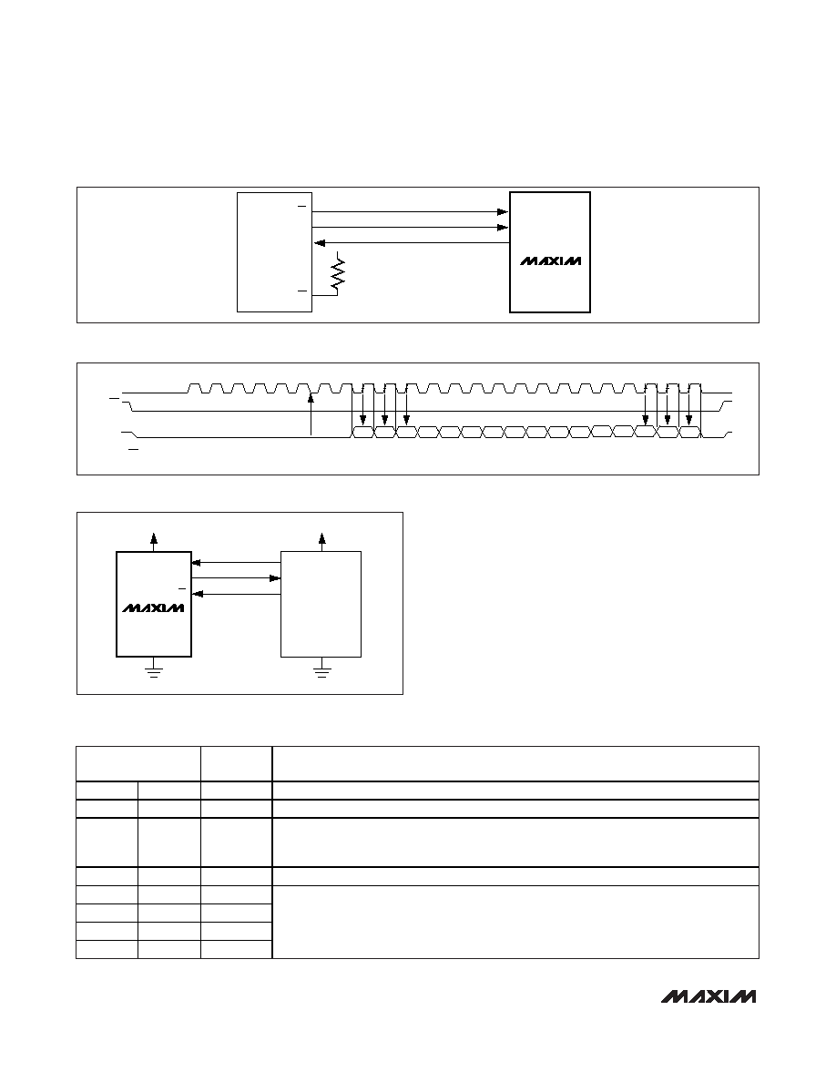
PIC16 with SSP Module and
PIC17 Interface
The MAX1162 is compatible with a PIC16/PIC17 micro-
controller (C) using the synchronous serial-port (SSP)
module.
To establish SPI communication, connect the controller
as shown in Figure 12a. Configure the PIC16/PIC17 as
system master, by initializing its synchronous serial-port
control register (SSPCON) and synchronous serial-port
status register (SSPSTAT) to the bit patterns shown in
Tables 1 and 2.
In SPI mode, the PIC16/PIC17 C allows 8 bits of data
to be synchronously transmitted and received simulta-
CS
QSPI
SCLK
DOUT
CS
SCK
MISO
VDD
SS
MAX1162
SCK
SDI
GND
PIC16/17
I/O
SCLK
DOUT
CS
VDD
MAX1162
Figure 11a. QSPI Connections
Figure 12a. SPI Interface Connection for a PIC16/PIC17
DOUT*
CS
SCLK
*WHEN CS IS HIGH, DOUT = HIGH-Z
MSB
20
16
D15
D14
D13
D12
D11
D10
D9
HIGH-Z
D1
D0
24
12
14
8
6
D8
D5
D4
D3
LSB
D7
D6
END OF
ACQUISITION
D2
Figure 11b. QSPI Interface Timing Sequence (CPOL = CPHA = 0)
CONTROL BIT
MAX1162
SETTINGS
SYNCHRONOUS SERIAL-PORT CONTROL REGISTER (SSPCON)
WCOL
BIT7
X
Write Collision Detection Bit
SSPOV
BIT6
X
Receive Overflow Detect Bit
SSPEN
BIT5
1
Synchronous Serial-Port Enable Bit:
0: Disables serial port and configures these pins as I/O port pins.
1: Enables serial port and configures SCK, SDO, and SCI pins as serial port pins.
CKP
BIT4
0
Clock Polarity Select Bit. CKP = 0 for SPI master mode selection.
SSPM3
BIT3
0
SSPM2
BIT2
0
SSPM1
BIT1
0
SSPM0
BIT0
1
Synchronous Serial-Port Mode Select Bit. Sets SPI master mode and selects
fCLK = fOSC / 16.
Table 1. Detailed SSPCON Register Contents
发布紧急采购,3分钟左右您将得到回复。
相关PDF资料
MAX11637EEE+T
IC ADC 12BIT 8CH 16QSOP
MAX11643EEG+T
IC ADC 8BIT 8CH 24QSOP
MAX11645EUA+T
IC ADC 12BIT I2C/SRL 1CH 8UMAX
MAX11647EUA+T
IC ADC 10BIT I2C 94.4KSPS 8UMAX
MAX1166BEUP+
IC ADC 16BIT 165KSPS 20-TSSOP
MAX1168BCEG+
IC ADC 16BIT 200KSPS 24-QSOP
MAX1183ECM+TD
IC ADC 10BIT 40MSPS DL 48-TQFP
MAX1184ECM+TD
IC ADC 10BIT 20MSPS DL 48-TQFP
相关代理商/技术参数
MAX1162AEUB-T
功能描述:模数转换器 - ADC RoHS:否 制造商:Texas Instruments 通道数量:2 结构:Sigma-Delta 转换速率:125 SPs to 8 KSPs 分辨率:24 bit 输入类型:Differential 信噪比:107 dB 接口类型:SPI 工作电源电压:1.7 V to 3.6 V, 2.7 V to 5.25 V 最大工作温度:+ 85 C 安装风格:SMD/SMT 封装 / 箱体:VQFN-32
MAX1162BC_B
制造商:MAXIM 制造商全称:Maxim Integrated Products 功能描述:16-Bit, +5V, 200ksps ADC with 10レA Shutdown
MAX1162BCUB
功能描述:模数转换器 - ADC RoHS:否 制造商:Texas Instruments 通道数量:2 结构:Sigma-Delta 转换速率:125 SPs to 8 KSPs 分辨率:24 bit 输入类型:Differential 信噪比:107 dB 接口类型:SPI 工作电源电压:1.7 V to 3.6 V, 2.7 V to 5.25 V 最大工作温度:+ 85 C 安装风格:SMD/SMT 封装 / 箱体:VQFN-32
MAX1162BCUB+
功能描述:模数转换器 - ADC 16-Bit 200ksps 4.096V Precision ADC RoHS:否 制造商:Texas Instruments 通道数量:2 结构:Sigma-Delta 转换速率:125 SPs to 8 KSPs 分辨率:24 bit 输入类型:Differential 信噪比:107 dB 接口类型:SPI 工作电源电压:1.7 V to 3.6 V, 2.7 V to 5.25 V 最大工作温度:+ 85 C 安装风格:SMD/SMT 封装 / 箱体:VQFN-32
MAX1162BCUB+T
功能描述:模数转换器 - ADC 16-Bit 200ksps 4.096V Precision ADC RoHS:否 制造商:Texas Instruments 通道数量:2 结构:Sigma-Delta 转换速率:125 SPs to 8 KSPs 分辨率:24 bit 输入类型:Differential 信噪比:107 dB 接口类型:SPI 工作电源电压:1.7 V to 3.6 V, 2.7 V to 5.25 V 最大工作温度:+ 85 C 安装风格:SMD/SMT 封装 / 箱体:VQFN-32
MAX1162BCUB-T
功能描述:模数转换器 - ADC RoHS:否 制造商:Texas Instruments 通道数量:2 结构:Sigma-Delta 转换速率:125 SPs to 8 KSPs 分辨率:24 bit 输入类型:Differential 信噪比:107 dB 接口类型:SPI 工作电源电压:1.7 V to 3.6 V, 2.7 V to 5.25 V 最大工作温度:+ 85 C 安装风格:SMD/SMT 封装 / 箱体:VQFN-32
MAX1162BE_B
制造商:MAXIM 制造商全称:Maxim Integrated Products 功能描述:16-Bit, +5V, 200ksps ADC with 10レA Shutdown
MAX1162BEUB
功能描述:模数转换器 - ADC RoHS:否 制造商:Texas Instruments 通道数量:2 结构:Sigma-Delta 转换速率:125 SPs to 8 KSPs 分辨率:24 bit 输入类型:Differential 信噪比:107 dB 接口类型:SPI 工作电源电压:1.7 V to 3.6 V, 2.7 V to 5.25 V 最大工作温度:+ 85 C 安装风格:SMD/SMT 封装 / 箱体:VQFN-32